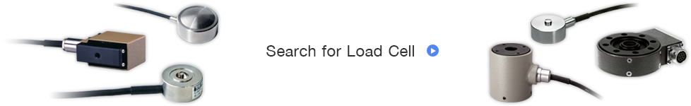
Tension / Compression Load Cell
TU-MBR(T)☐☐N-G3
TEDS RoHSTension measurement, In-line load management
Made in Japan
- Features
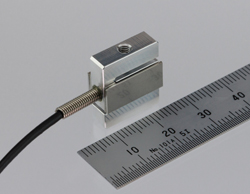
- Ultra Compact, Safe overload of 500%
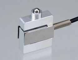
Load button (Option)
Specifications
| Model | Unit | Rated Capacity (R.C.) | ||||||||||||
|---|---|---|---|---|---|---|---|---|---|---|---|---|---|---|
| TU-MBR(T)☐☐N-G3 | N | 0.5 | 1 | 1.5 | 2 | 3 | 5 | 10 | 20 | 50 | 100 | 200 | 500 | |
| kN | 1 | 2 | 3 | 5 | 10 | 20 | 30 | 50 | 100 | 200 | 300 | 500 | 1000 | |
| Rated Capacity (R.C.) | Natural Frequency | Weight (g) | |
|---|---|---|---|
| 2N | 204gf | 1.47kHz | 5g |
| 5N | 510gf | 2.45kHz | 5g |
| 10N | 1.02kgf | 2.81kHz | 5g |
| 20N | 2.04kgf | 2.92kHz | 5g |
| Model | TU-MBR(T)☐☐N-G3 |
|---|---|
| Maximum Load Limit | 500%R.C. |
| Rated Output (R.O.) | approx. 0.4mV/V |
| Linearity | 0.1%R.O. |
| Hysteresis | 0.1%R.O. |
| Repeatability | 0.1%R.O. |
| Safe Excitation Voltage | 5V |
| Input Terminal Resistance | 350Ω±5% |
| Output Terminal Resistance | 350Ω±5% |
| Insulation Resistance | 1000MΩ or more (DC50V) |
| Compensated Temperature Range | -10 - 60℃ |
| Operating Temperature Range | -20 - 70℃ |
| Temperature Effect on Zero Balance | 1%R.O./10℃ |
| Temperature Effect on Output | 1%R.C./10℃ |
| Cable | Direct connection with φ2 4-core shielded robot cable for 1 m (to built-in TEDS part) φ3 6-core cable lead about 170mm from built-in TEDS part |
| Mounting | 2×M3 tap on bottom(Fixing bolts used for the 2×M3 should be 4.5mm or less in depth.) |
| Environmental Regulations | RoHS 10 |
| Body Material | Aluminium |
| TEDS | inside cable lead |
| Others |
|
Outline Dimensions
Units:mm